In our previous article, we completed our look at mechanical properties by discussing how allowable stresses are determined. In this article we are going to look at the last pieces of information we need to conduct a pipe stress analysis, i.e. stress intensification factors and flexibility factors.
When engineers conduct a pipe stress analysis, they construct a mathematical model of the piping system. The basic elements of the model are beam elements because, as far as loads other than pressure are concerned, a piping system is essentially a combination of connected beams. That’s fortunate because the equations for stresses in a beam are simple and exact; no approximations are required. Unfortunately, only pipe itself behaves as a beam element. The other components in a piping system, i.e. the fittings such as elbows, tees, reducers, etc., display more complex stress behaviors compared to the pipe.
So in order to correctly predict the stresses in the fittings, we need to apply “fudge factors” to the stresses calculated for pipe. These fudge factors are called stress intensification factors or “SIFs”. For FRP fittings, SIFs are defined as the ratio of the maximum stress in the fitting to the maximum stress in a pipe when exposed to the same loading. For example, let’s assume that a section of pipe is exposed to a bending moment equal to M. This could be the bending moment due to the weight of the pipe and contents midspan between two supports. The maximum bending stress in the pipe is simple to calculate and is equal to:
\[S_b=\frac{M}{Z}
\]
where:
Sb = Bending stress
M = Bending moment
Z = Section modulus of the pipe. This is a geometrical property of the pipe dependent only on the diameter and thickness of the pipe.
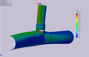
Now, if there were a fitting such as an elbow or a tee at the midspan between the supports and therefore exposed to the same bending moment, the maximum stress in the fitting would likely be different (and probably higher) than in the pipe. The Finite Element Analysis (FEA) image below, of a reducing tee, illustrates how the local stresses in a fitting can be much higher than in the adjacent pipe.


