Pressure Design of FRP Piping Components – Fittings and Joints

In our previous article, we took our first look at pressure design of piping components by looking at pipe. We are going to continue that discussion by looking at pressure design of FRP pipe fittings and joints.

As we noted in our last article, pipe is by far the simplest component to design in any piping system. The stresses in a pipe when exposed to pressure are:

\[
S_h=\frac{P \cdot I D_s}{2 \cdot T_s} \quad\text { and }\quad S_{a x}=\frac{P \cdot I D_s}{4 \cdot T_s}
\]

where:
Sh = Hoop stress
Sax = Axial stress
P = Pressure
IDs = Inside diameter of structural wall
Ts = Thickness of structural wall

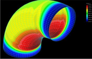
The situation isn’t quite so simple for most fittings. The geometry of fittings gives rise to local stresses within the fitting that can be significantly greater than those calculated using the equations above. The most common method for dealing with these higher stresses is to include a “fudge factor” with one or both of the above equations. This fudge factor is called the pressure stress multiplier. It is usually designated by the letter “m”, and it represents the ratio of the maximum pressure stress in the fitting to the pressure stress in an equivalent pipe.

The equation for hoop stress would then become:

\[
S_h=\frac{m \cdot P \cdot I D_s}{2 \cdot T_s}
\]

For example, in a long radius elbow of uniform thickness, the maximum hoop stress in the elbow is 1.25 times that in a pipe, so m = 1.25. This means that a long radius elbow should be at least 1.25 times as thick as a pipe to provide the same factor of safety against burst. (This statement is only true if the pipe and elbow are manufactured using the same type of laminate; a situation that is most often not the case. The elbow could be thinner or thicker than the 1.25 times depending on the relative strengths of the elbow and pipe laminates).

This finite element analysis (FEA) graphic shows the distribution of stresses around an FRP elbow

If we looked closer at the distribution of the pressure stresses around the circumference of the elbow, we would learn that the stress is greatest on the inside radius of the elbow, and least on the outside radius. This can be seen in this Finite Element Analysis (FEA) graphic, where the red areas represent the higher hoop stresses and the green areas represent the lower hoop stresses (the blue areas are at the joints where the total thickness has been increased by the joint laminate).

This non-uniform distribution of stresses means that the thickness need not be uniform to address the higher stresses. By applying the additional thickness only where the stresses are higher, it is possible to manufacture a more cost-effective elbow. This approach would allow us to avoid wasting material by applying the additional thickness only where it’s required.

Like the pipe, we still need to know the strength of the laminate before we can determine what the thickness needs to be. Very few fittings are tested under long term pressure testing (e.g., ASTM D2992). It is more common to conduct short term burst testing of fittings to determine laminate strength (e.g., ASTM D1599), but testing 5 samples (as required by ASTM D1599) of any fitting can become very expensive. It is more cost effective and much more common to conduct short term testing of coupons cut from typical laminates (e.g., ASTM D638). This latter method is possible in fitting laminates as the materials are such that they can usually be applied on a flat sheet (and absence of coupon curvature is usually a requirement for the relevant tensile test methods). The same can’t be said for the filament wound laminates used in pipe. Once the laminate strength is known, a design factor is applied to the laminate strength to calculate an allowable stress, and the required fitting thickness is calculated using the modified equation above.

This approach of applying a pressure stress multiplier to the basic pipe equations can be used for almost any fitting. We just have to use appropriate values for the pressure stress multiplier (m). As we’ve already seen, “m” for an elbow is 1.25. But some fittings, tees for example, have a much larger “m”. A typical value for “m” of a tee is about 2.5, so a tee has to be significantly thicker than a pipe to provide the same factor of safety.

This same approach can also be applied to butt joints. Although butt joints are similar in shape to that of pipe (i.e. cylindrical), the discontinuity in the geometry where the pipe ends meet results in stress concentrations within the joint. Applying a pressure stress multiplier “m” of 1.67 will result in an acceptable factor of safety to the joint design. 

The design approach just described is an appropriate method for designing fittings and joints, but we haven’t yet actually proven that the component is adequate. Recall that the approach utilized strength properties from flat sheet laminates and application of a “fudge factor” (i.e. the pressure stress multiplier). For example, we haven’t yet demonstrated that the fudge factor was adequate, or that we applied the reinforcements appropriately. To provide evidence that the component actually achieves the factor of safety required, testing of the actual component is necessary. This is the purpose of proof testing (also called proof of design testing). There are several methods that can be used for proof testing. The first of these is to actually burst the component in accordance with ASTM D1599. While this is the most direct approach, it requires specialized equipment – particularly for larger diameter components, and it carries with it some safety concerns. Unlike filament wound pipes, which typically fail by weeping, fittings often fail by actually bursting. A lot of energy can be released during these sometimes “exciting” events, so appropriate precautions need to be taken to avoid damaging equipment and facilities, and more importantly, for ensuring the safety of the personnel involved.

Proof testing is more commonly carried out by pressurizing to lower levels, but holding the pressure for longer periods of time. For example, ASME NM.2* requires that the component be pressurized to 4 times its rated pressure for 1 hour without leaking. This is the method that RPS uses to verify adequacy of its fittings and joints.

In our next article, we will conclude our look at pressure design of piping components by looking at the design of flanges.

* ASME NM.2-2018 Glass-Fiber-Reinforced Thermosetting-Resin Piping Systems

Previous article in the series: Pressure Design of FRP Piping Components

Next in the series: Pressure Design of FRP Piping Components – Flanges