In our previous articles, we looked at pressure design of piping components including pipe, fittings, and joints. In this article we are going to conclude our discussion on pressure design with a look at FRP pipe flanges.
Flanges present the greatest design challenge of all standard piping components. The theory underlying design of flanges is very complex, and the design methods are typically trial and error, i.e. a flange configuration is first assumed, and then it is checked for stresses. If the stresses are not acceptable, another configuration is assumed, and the stresses checked again. Flange design theories are generally complex for several reasons:
- A flange is not just a simple component like an elbow or a reducer; it is actually composed of several components acting together, i.e. the flange ring, the flange hub, the bolts, and the gasket.
- The individual components of the flange are typically composed of materials with significantly different properties. For example, the bolts are metallic and hence very stiff; the gasket is typically elastomeric and hence very flexible.
As a result of these issues, most flange design approaches are either “simplified” elastic analyses, or even empirical in nature.
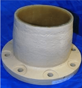
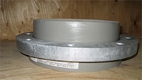
The most commonly used design methods for contact molded, full-face FRP pipe flanges (see Figure 1) are those found in ASME NM.21 ASME RTP-12 and ASME BPV Code Section X3. The methods are very similar, and for the same inputs, will yield virtually identical results. The methods are derived from the design method for metallic flanges found in the ASME BPV Code Section VIII4 for metallic pressure vessels. That design method applies to raised-face configurations where there is no contact between the flanges out beyond the bolt circle. Such a flange configuration results in high longitudinal hub stresses arising due to bolt tightening and operating loads, which would be difficult for a material like FRP to accommodate. For this reason, FRP flanges are most often designed with flange contact over the entire flange face. This configuration substantially reduces the longitudinal hub stresses. But given the greater contact area of the gasket, the initial bolt loads must be much higher to effectively seat the gaskets. To limit the bolt torques to reasonable levels requires the use of soft gaskets. Unfortunately, the soft gaskets limit the use of this configuration to relatively low pressures, e.g. 150 psi.


