In the last several articles, we looked at the piping information required to properly analyze an FRP piping system. This information included the elastic properties (modulus values and Poisson ratios), the strength properties (allowable stress envelopes), and the Stress Intensification Factors and Flexibility Factors. We’re now at a point where we can discuss how an FRP pipe stress analysis is actually carried out.
As previously mentioned, there are inputs to the pipe stress analysis that would be the same regardless of the choice of piping material. These include pressure, temperature, and density of the fluid, which are dictated by the process conditions. They also include the occasional loadings such as wind and seismic. The Owner (or Owner’s agent) will typically define the basic occasional load parameters such as wind speed and seismic accelerations, as well as the building code to which all plant equipment and systems must be designed. The Designer will then utilize the provisions of a building code standard such as ASCE 71 to determine the actual loads that should be included in the pipe stress analysis.
The Designer creates a computerized model of the piping system with a pipe stress analysis program such as CAESAR II or AutoPIPE. This task involves a number of steps including:
- Breaking the piping system into discrete elements, each of which represents a small portion of the piping system. The elements are defined by the “nodes” at each end of the elements. The choice of node locations is up to the Designer, but for accurate representation of the piping system, nodes are required at each change of direction or material, at all in-line equipment, and at all restraints (supports and terminal points). Additional nodes would be included at any location where the Designer requires output information. An example of this would be at the midpoint between supports so that the deflection between supports can be determined.
- Defining the appropriate geometric properties of each element, i.e. diameter and thickness of the pipe, and length and orientation of the element.
- Defining the design conditions/loadings including pressure, temperature, weight of the pipe and contents, and seismic and wind loadings.
- Assigning the appropriate material properties to each element including modulus values and allowable stresses.
- Applying the appropriate Stress Intensification Factors and Flexibility Factors to the fittings.
- Defining the support types and locations.
- Defining any imposed displacements on the piping system, e.g. thermal growth of a vessel to which the piping is attached.
- Creating the appropriate load cases to ensure all load combinations of interest are analyzed.
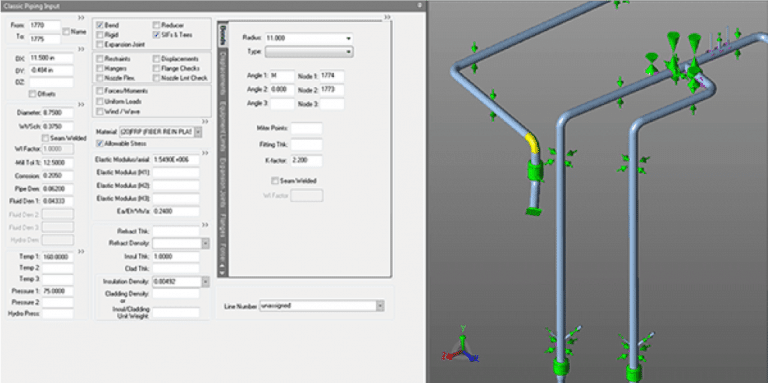
An example of the input screen (CAESAR II) defining the properties of a particular element is shown below: