Conquering Challenges with RPS: a tale of failed steel pipe and a call for innovation
Products provided: “A” Series Corrosion / Abrasion Resistant FRP Pipe
Services provided: Pipe and fitting component design, pipe system analysis, support design and supply, design of auxiliary steel, and QA of the FRP field joints
Industry: Power Generation
Location: USA
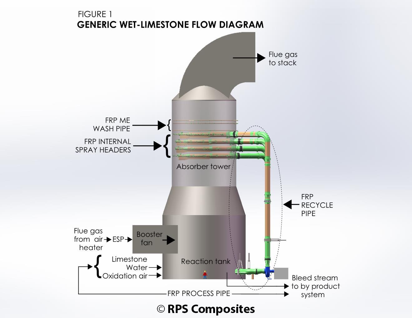
In 1996, an electric utility in the United States added pollution control equipment to an existing 2000 MW coal fired boiler to remove sulfur dioxide from the boiler flue gases. Wet limestone open spray tower flue gas desulphurization (FGD) scrubbers were added downstream of the boilers. In open spray tower wet FGD systems, flue gases enter the tower and as they rise to the top, limestone slurry is sprayed counter current to the gases. The sulphur dioxide in the flue gases is absorbed by the limestone slurry scrubbing liquor. The slurry is recycled from a sump in the bottom of the tower and pumped through external recycle slurry pipes to absorber internal spray pipes near the top of the absorber.
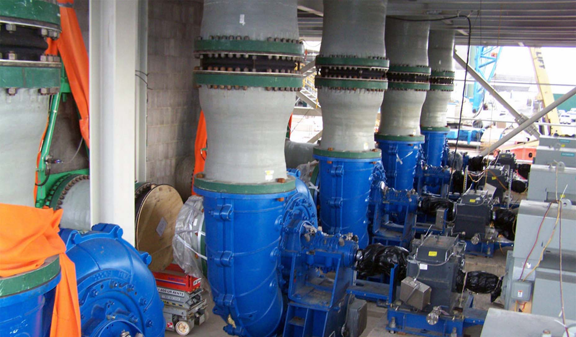
The FGD plant for this 2000 MW station included 10 absorber towers with 6 spray levels in each absorber. The limestone slurry reagent is both abrasive and corrosive. The original recycle slurry piping as supplied with the FGD plant was rubber lined carbon steel. The plant was experiencing significant problems with the rubber lined steel pipe within only a few years of start up. The rubber lining was blistering in areas. In some instances the blisters were failing causing rubber to peel away from the pipe. This rubber would then become lodged in spray nozzles inside the absorber tower. Permeation of the fluid through the rubber lining was causing corrosion of the steel pipe and leaks through the pipe wall.
After several years of significant maintenance cost associated with repairing and relining the steel pipe the plant operators and engineers evaluated their options for replacement of the rubber lined carbon steel pipe. Alloy pipe, rubber lined carbon steel pipe, and RPS “A” series erosion/corrosion resistant frp pipe were considered. Based on proven performance and cost savings RPS “A” series pipe system was chosen. RPS scope of supply included pipe and fitting component design, pipe system stress analysis, support design and supply, design of auxiliary steel, and Quality Assurance of the FRP field joints.
FRP Pipe and Fitting Construction, and Design
The pipe and fittings were constructed using a fire retardant vinyl ester resin and included RPS proprietary “A” series reinforced erosion resistant liner. The “A” series pipe system has a proven track record in over 150 FGD plant installations dating back to 1970.
The pressure rating of the pipe system was specified at 100 psi. The filament wound pipe structural wall thicknesses were established using hydrostatic design stresses from testing in accordance with ASTM D2992. The fitting structural walls and joint designs were determined in accordance with the requirements of ASTM D6041. Flanges were qualified in accordance with ASTM D5421.
Pipe System Analysis
The entire recycle pipe system was modeled and analyzed using Caesar II pipe stress analysis software. The stress analysis was conducted in accordance with the requirements of the pipe codes with the following additional criteria: FRP does not yield in the same manner as steel and therefore higher allowable stresses were not used when analyzing displacement type load cases such as thermal. All load cases were analyzed as corroded. The corrosion allowance used was equal to the full erosion liner thickness. Torsional stresses were included in the code stress equations.
Finite element analysis was also carried out at high stress support locations and in some cases support designs were stiffened to reduce local deformation of the FRP pipe. F. E. analysis was also conducted at the anchor support on the vertical riser pipe. This analysis found very high radial stresses in the FRP shear collar. As a result a steel strap was added to the design of the shear collar and this strap was pretensioned at the time of installation to ensure radial stresses were contained.
Installation
Removal of the existing rubber lined carbon steel pipe and installation of the new FRP pipe and supports was the responsibility of the plant owner. This work was contracted to a mechanical contractor who regularly did work at the plant. RPS was contracted to supply quality assurance inspection services for the FRP field joints throughout the installation for the first two absorber towers.
Upon completion of installation of the first two towers RPS carried out a complete system inspection to verify supports were properly installed. This inspection revealed a number of locations where sliding supports had been improperly installed and were restraining the free axial and or lateral movement of the pipe. These were documented and then corrected by the installation contractor prior to hydro testing and start up.
Installation of the pipe continued on the remaining 8 absorber towers in coordination with required plant operation. All 10 towers were retrofitted, and it is expected this recycle pipe will provide more than twenty years of maintenance free service providing the plant owners with an excellent return on their investment.
Conclusions
Fiberglass reinforced plastic pipe systems have the potential for performance and cost advantages over other piping materials in many applications. In order to realize these advantages, plant owners and pipe designers need to pay careful attention to material selection, pipe and fitting design, pipe system stress analysis, and installation. While the ASME pipe codes do not yet define requirements for FRP pipe, there are well-established ASTM standards and specifications and proven design and installation practices that will help ensure realization of the full advantage of FRP pipe systems.
We’ve developed a number of piping systems, which have been designed to provide outstanding resistance to a wide range of chemical environments. Download our Guide to explore the RPS family of HPPE (High Performance Pre-Engineered) piping systems.